Introduction
Over the past few years I’ve become interested in tinkering with keyboards. I have a Keychron Q1 Pro and K10 that are customized with new paint and switches etc… But a I’ve always dreamed of building a Model M keyboard with modern mechanical switches. They look so good! I can appreciated the feel and sound of the Model M, but its just not practical for office use. Its far too loud. So began the project of trying to make a custom PCB to swap into a donor Model M. I quickly found that I do not have the expertise to design such a project from scratch. But while I was pursuing Google Images I found a GitHub post from Dcpedit. (Link) Dcpedit had made a repository that had everything I was looking for. They documented the entire process and there was very little for me left to figure out once the time came to start ordering and assembling.
Gathering Supplies
The table below outlines all of the parts I purchased along with their part numbers where applicable. I attached a rough price estimate at the time of order. Most of the prices are probably pretty stable but the order from JLCPCB was affected by tariffs making it substantially more expensive. I also bought extra of some parts because I was unsure how hard it was going to be to solder since I’m a novice at best. So you could probably cut some corners as well.
Digikey Order (~$52 USD)
3x 30pin FCC Connector – OR1179CT
1x 30pin FCC Cable – WM19610
3x Green 3mm LED – 732-5008
3x Clear 3mm LED – 365-1467
3x 470ohm Resistor – CF18JT470RCT
3x 10kOhm Resistor – CF14JT10K0CT
1x 22kOhm Resistor – CF14JT22K0CT
65x BAV70 Didoes – 1727-2912-1
1x BlackPill STM32F411 – 1738-DFR0864 (Includes 2x headers)
6x Kailh Switch Sockets – 1528-4958 (Packs of 20x)
Amazon(~$36 USD)
60x M2.5x4mm+6mm Standoff screws – Link (4mm instead of 6mm may be helpful. These had to be ground down to fit)
1x DUROCK V3 Stabilizers –Link
60x m2.5×4 Button Screws – Link
JLCPCB Order (~$115)
5x 1.2mm FR4 Main board
5x 1.6mm FR4 Daughter board
Ebay (~$130)
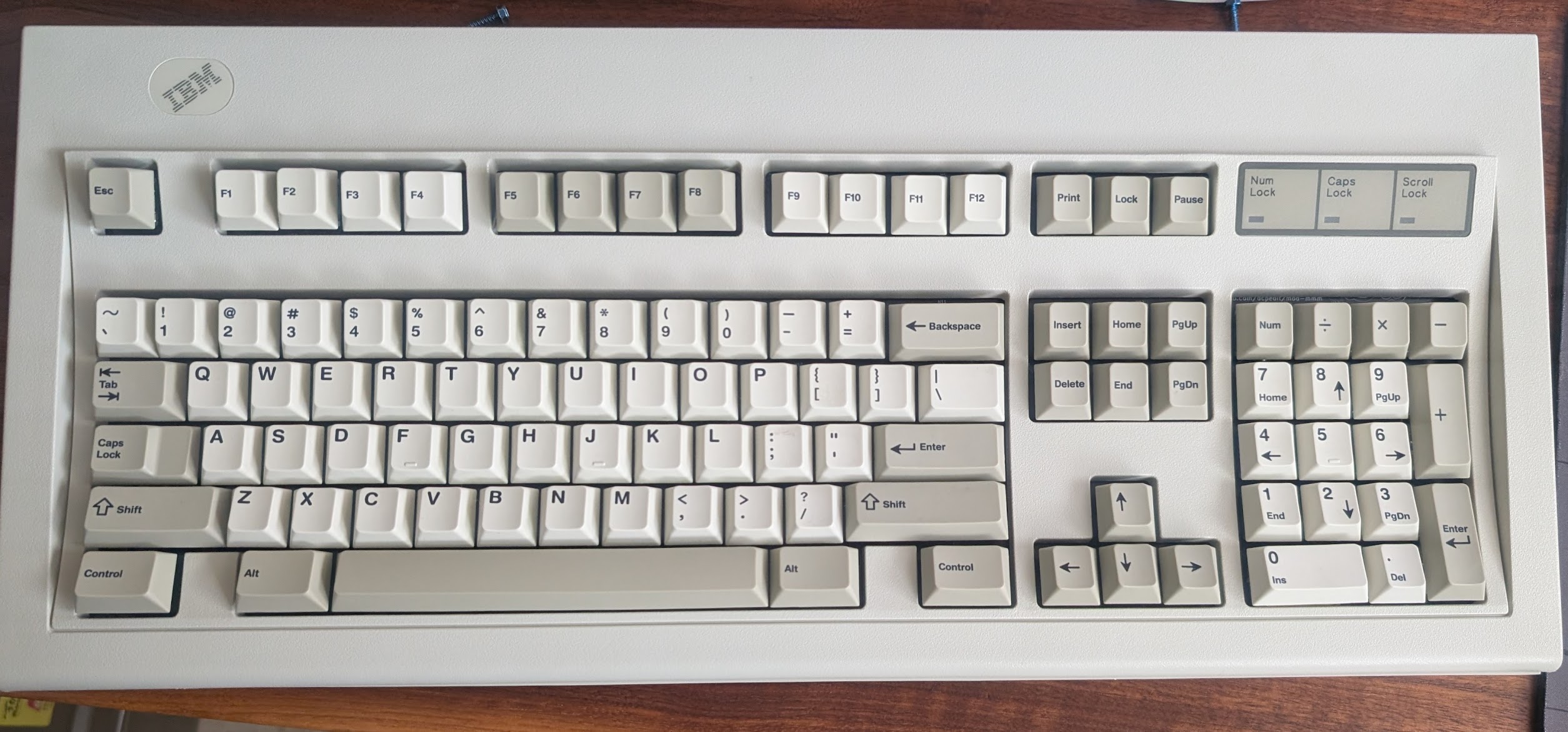
IBM Model M donor Keyboard
PCB Assembly
The assembly of the PCB’s were pretty self explanatory. I think the most important thing is to pay attention and take it slow. I made a few mistakes during the solder process that could have been avoided if I took more time. The soldering its self was not very difficult. The hardest part in my opinion were the diodes followed by the ribbon cable connector. I think anyone with a decent understanding of how soldering works could do this. My previous experience was soldering USB cables and not much else.
Tools Required
- Good Quality Soldering Iron
- Brass sponge for tip cleaning
- Flux
- Lead based solder
- Solder wick (especially helpful for 30pin)
Step 1: Solder the Daughter board
I first began by soldering the daughter board. For this I started by first soldering the 4 pin header to the BlackPill. Once that was complete I mounted the 2 30pin headers to the PCB and soldered then into place. Once those were held at the base I soldered the 4pin head as well to affix the Blackpill. Once it was held in place I was able to solder the rest of the pins on the top of the pill as well. Soldering the headers like this makes it non removable incase you wanted to reuse this module in the future without de soldering.
Once the module was soldered I moved over to the 30pin. I started by first getting solder on the pads then attaching the two support pins on either end. Make sure to keep the data pins aligned with there respective pads while doing this. I was able to spread solder to each pad/pin without much issue but I did cross a few pins. This is where it came in handy to have soldering wick available.
Once both of these components have been soldered I connected the ribbon cable and used it to test conductivity to make sure each pin could reach the BlackPill. They all passed first try thankfully! Note the first and last pin are grounds. The pin on the far right also grounds to the PCB so it can’t be traced. You can refer the the schematic in KiCad to see this if needed.
Step 2: Solder the main PCB
Soldering the main board was a similar process to the daughter board. I started by pre-soldering all of the pads. Once that was complete I did all of the switch sockets. They were pretty quick to do, the only thing to make sure you get correct is the orientation. I had a few issues with this, if you get them upside down they will block the stems of your switches. Once the sockets were all on I soldered the diodes followed by the 30pin, transistors and LED’s. These were all relatively easy, although the size of the diodes made them a bit difficult at times.
One important thing to note would be to pre bend the main PCB for 24hrs or so before soldering. I didn’t do this step and it caused me a few issues. During initial assembly I had three or four diodes break at the solder joint.
Step 3: Disassemble the Model M donor
Next was to disassemble the Model M. Once you unscrew the back and get the cover off you should see the keys and the plate they are mounted too. You should be able to carefully detach the ribbons and pull it out. Once removed you will need to use a razor to ‘cut’ the black supports that are cast through the metal back plate. Once they are all cut you should be able to carefully remove the capacities sheets/key assemblies. They are no longer retained at this point so the keys will want to fall out if your not careful. Once that is all done you are able to remove the main controller.
Step4: Attaching the stabilizers
At this point you are able to attach the stabilizers to the PCB. I chose to use screw mount stabs because of issues I had using surface mount stabs in the past. Because these require screwing from the back you have to do it before you attach it to the back plate. These are pretty straightforward to mount and the Durock V3 stabs worked great for me. They mounted to the pre drilled stab holes without issue.
Step 5: Attach the PCB to the back plate

To attach the PCB to the back plate I used brass standoffs. I used 4mm deep standoffs with a 6mm base to push through the plate. In hind sight I think 4mm for the base would have been better because I did have to grind some of them down towards the bottom where the space bar is located. I didn’t put too much thought into placement. I basically just stuck them anywhere there was a stock hole. The PCB design has screw mount holes in a bout 90% of the stock screw locations which in my opinion is more that enough support.
Once the standoffs were attached I was able to mount the PCB. To try and limit stress I would start at the F row and work my way down slowly. I tried to keep the bend even across the board and avoid introducing too much bend all at once. I did have to re mount the PCB once because of a few bad joints on the diodes. The solder didn’t hold up to the bend and had to be re flowed. I strongly recommend testing the PCB with switches before mounting. It does add extra work but it will save headache in the future. Remounting the PCB for one broken switch is no fun, trust me.
Step 6: Switches and Key caps

This step was my favorite because you could finally see the keyboard start to take its final form. This step is pretty similar most mechanical keyboards, you just need to insert the switches in there respective places and then install the key caps.
I did run into a few quirks during this step. I had a pin issue with two switch mounts and a short from the switch. The short from the switch was a simple fix. The pin was poking too far down and was shorting to the back plate. To fix this I just trimmed the pin so its shorter and it stopped giving issues. The switch mounts were are bit harder to figure out but the fix was simple. The teeth that bite the pins of the switch when inserted were lose. To fix it I just used a needle and bent the switch teeth so they bit the pin better.
Step 7: Flashing the firmware
To flash the firmware I used QMK Toolbox. I tried using the web tool to create my own firmware but was having issues. The PCB layout for the mmmModel M is no longer listed and I didn’t want to go through the hassle of adding it or finding another one that is compatible.
How to Flash the Blackpill:
- Open QMK and plug in the controller
- Place the controller into flash mode by holding Boot0, then press RESET and release Boot0
- If done properly the Software will acknowledge it on screen.
- Leave the settings in QMK as they are and open the .bin file located in
"%Directory%\mod-mmm-master\firmware\blackpill\dcpedit_modmmm_standard_via.bin" - Click “Flash” and it should succeed. You are then safe to unplug the controller.
Step 8: Final Assembly
Now they the Controller is flashed you can do the final assembly. Since the key switches are already mounted to the black plate this step is pretty straightforward. I just had the place the controller into the case and then place the plate over top. Once that was in I could plug in the 30 pin ribbon cable. I did have issues with the Controller PCB being lose so I taped it down with electrical tape. From there I was able to screw it together. After that it was finally ready to plug in and be used!
Sound Test:
Here is a short sounds test of it completed for those who are curious.
Conclusion:
I had a lot of fun doing this project. It taught me a lot. Even though I did not create the PCB design, I learned a lot from assembling it. I was able to practice my soldering and solder parts that for me are quite small. It also helped with my understanding of how a keyboard actually works under the hood which was cool. They are simple but when you see one online you always think they would be so complex if you wanted to make your own. But in reality they are not as complicated as you think. Of course if you make you own PCB its considerably harder, but there are a lot of 3rd party PCB’s posted and sold they you could use instead of making your own.
The performance and reliability of this keyboard has been good as well. Once completed I haven’t had any issues and its worked great. I’ve been using it daily for the last few week to play games and even write this article.
I would definitely consider building something like this again.
Leave a Reply