Tag: technology

  • Display time dynamically on a I2C LCD using a Blackpill

    Display time dynamically on a I2C LCD using a Blackpill

    Goal

    This project is the second iteration of my first project where I displayed the time generated on the STM32 to Putty. Instead of just displaying to Putty, this time I wanted to display the time and date to a LCD. Pretty simple overall, nothing too fancy. I do want to configure it though so that the display updates dynamically so that I don’t refresh the whole LDC causing flashing. The process to do this ended up being quite a bit more complicated than I expected but after a lot of Googling and trial and error, I was able to get it figured out. Like my other article I found CircuitGator on YouTube extremely helpful. You can find the video I used to configure i2c here.

    STMCube Configuration

    The only setting that needs to be configured in the GUI is RTC under the timers tab. In the settings page for RTC all that needs to be configured is the check box for activating the clock source and the calendar. For ease of use you can also configure the parameters so that the code generates with the correct time. This can be changed manually in the main.c file as well if desired. I also changed the HCLK in the Clock configuration tab to 100Mhz to maximize CPU performance but this is not required.

    After these changes the code can be generated.

    Code Generation

    Dynamic LCD Updating

    Before I get into the code and what each section does, I want to give a brief explanation of the overall process of how I’m interacting with the LCD and why. Instead of refreshing and re-printing all of the data to the LCD, I only want to update the portion that changes. For instance the section that displays the date will only change once a day. So instead of reprinting that each second, I only reprint it if it changes. To achieve this I have separate processing for each value on the LCD. Without this processing the LCD takes a lot longer to change and flashes each second. With processing it will update each second and only changes the values that increased.

    Driver Installation

    Now that the GUI settings have been configured it is time to do the fun part. Before we start making the code you have to import the i2c driver files into your src and inc directories. These are both under %Projectname%>Divers>STM32Fxx_HAL_Driver. You can just copy and past via the GUI. The driver files can be found here. The .c file goes in the Src folder and the .h file goes into the Inc folder. Once copied, open liquidcyrstal_i2c.h in the Inc folder and verify the #include statement matches your STM chip. So if you have a STM32F4 it should be #include "stm32f4xx_hal.h". And STM32F1 would be #include "stm32f1xx_hal.h" You will also want to scroll down till you see where see the i2c address being defined. For me, I used a Inland 1602 LCD so I had to update my address to #define DEVICE_ADDR (0x27 << 1). The 0x27 portion is all you should need to change. You can get this number from your LCDs datasheet or use a i2c address finder program which is what I did.

    Main.c Configuration

    Now that the driver has been imported we can configure the main.c file. We first start with our includes which import the library needed for our while loop and private code to word.

    /* USER CODE BEGIN Includes */
    #include "stm32f4xx_hal.h"  // Required for i2c calls
    #include <stdio.h>  //Required for snprintf
    #include <string.h> // Required for strncmp
    /* USER CODE END Includes */

    Private User Variables

    Next we can declare our private Variables. This is where my code may get a bit messy. The “buffer#” buffers are used to store and print to the LCD. The corresponding “buffer#temp” buffer is used in the strcmp function to compare string for changes. This is apart of how I only refresh the part of the LCD that changes.

    /* USER CODE BEGIN PV */
    char buffer[5];
    char buffertemp[5];   // Used for String Comparison
    char buffer1[5];
    char buffer1temp[5];  // Used for String Comparison
    char buffer2[5];
    char buffer2temp[5];  // Used for String Comparison
    char buffer3[5];
    char buffer3temp[5];  // Used for String Comparison
    char buffer4[5];
    char buffer4temp[5];  // Used for String Comparison
    char buffer5[5];
    char buffer5temp[5];  // Used for String Comparison
    /* USER CODE END PV */

    User Code 2

    Once we have declared our character buffers we can now begin interacting with the LCD. This portion of code runs once during the boot and does not continue to loop/change after start. RTC Time and Date functions define the sDate and sTime calls so that we can use them in the while loop and get their sub values. After this I can then initialize and clear the LCD and type the labels for each row. These are typed once at boot and not refreshed. If they were typed in the while loop it would keep refreshing with the same text and cause flashing and increased latency.

      /* USER CODE BEGIN 2 */
      RTC_TimeTypeDef sTime;
      RTC_DateTypeDef sDate;
    
      HD44780_Init(2);         // Initialize LCD
       HD44780_Clear();        // Clear LCD of data
       HD44780_Backlight();    // Enable backlight
       HD44780_SetCursor(0,0);    // Set location to row 1
       HD44780_PrintStr("Time:"); // Type "Time:" on row 1
       HD44780_SetCursor(0,1);    // Set location to row 2
       HD44780_PrintStr("Date:"); // Type "Date:" to row 2
      /* USER CODE END 2 */

    While loop

    The last section we needed to work on is the while loop. This part is two separate ‘sections.’ They are in the same loop statement but the first section does the processing and comparison for the time while the second section does the date. It is quite a long statement but when you break it down its quite simple. The first portion uses HAL to get the time and date. It grabs this data in binary and assigns it to sTime and sDate. This grabs updated data and assigns it to the values to later be read in the next section. To make the next sections easier to understand, I will only explain how I get the seconds from RTC and display it to the LCD. Each variable like the month or hour follow the same logic, just in their own statements.

    To get display the seconds I first use snprintf to grab and format the data. The data is grabbed by sTime.Seconds and because I included the "%02d" it formats it as 2 characters. For example 2s would be 02 and 10 would be 10. This integer is then assigned to the corresponding temp buffer which in this case is buffer2temp. This buffer does not get sent to the LCD but is instead used for comparison. Assume this function ran and assigned the value 06 to buffer2temp for the next section

    Now that the RTC binary info has been converted to a string and stored in buffer2temp I can use the strcmp function which compares the existing/previously printed variable(buffer2) with the most recently generated variable stored in buffer2temp. Upon the initial first run buffer2 has no value so it is considered different during comparison. For the sake of this explanation we will assume it has been running for 5s so the value last printed was 05. This means buffer2 currently has a value of 05. When the strcmp runs it compares buffer2(05) with buffer2temp(06). Since this value is different it initiates the code in the “else” section. If these values are equal no action is taken and the loop continues. When no action is taken the LCD does not update the correspond section displayed on the LCD. But since in this example the else section was activated I run another snprinf statement. This is the same function as the one that created the temp value but instead stores it in buffer2. I then use HD44780_SetCursor to set the cursor position. Since I want to print on the 7th character in the first line I use column 6 and row 0. HD44780_PrintStr is then called and is assigned the value buffer2 so that it can then be printed to the LCD.

    This same logic loop is used for printing the hours, minutes, seconds, date, month and year. Looking back on this there are definitely things I could have done more efficiently, but as a starting place for interacting and printing to the LCD it does work. If I were to rework this I would probably just assign buffer2temp to buffer2 instead of doing a duplicate snprintf statement in the strcmp loop.

    The final line in the while loop is HAL_delay(). All this does is tell the loop to restart every 1000ms.

        /* USER CODE BEGIN 3 */
    	  // Get the current time and date from RTC
    	  HAL_RTC_GetTime(&hrtc, &sTime, RTC_FORMAT_BIN);
    	  HAL_RTC_GetDate(&hrtc, &sDate, RTC_FORMAT_BIN);
    
    	  // Format time and date into a string
    	  snprintf(buffertemp, sizeof(buffertemp), "%02d:",
    	  	sTime.Hours);
    	  snprintf(buffer1temp, sizeof(buffer1temp), "%02d:",
    	  	sTime.Minutes);
    	  snprintf(buffer2temp, sizeof(buffer2temp), "%02d",
    	  	sTime.Seconds);
    	  if (strcmp(buffer, buffertemp) == 0) {
    	          // Strings are equal
    	      }
    	      else {
    	    	  snprintf(buffer, sizeof(buffer), "%02d:",
    	    			  sTime.Hours);
    	    	   HD44780_SetCursor(6,0);
    	    	   HD44780_PrintStr(buffer);
    	      }
    	  if (strcmp(buffer1, buffer1temp) == 0) {
    	          // Strings are equal
    	      }
    	      else {
    	    	  snprintf(buffer1, sizeof(buffer1), "%02d:",
    	    			  sTime.Minutes);
    	    	   HD44780_SetCursor(9,0);
    	    	   HD44780_PrintStr(buffer1);
    	      }
    	  if (strcmp(buffer2, buffer2temp) == 0) {
    	          // Strings are equal
    	      }
    	      else {
    	    	  snprintf(buffer2, sizeof(buffer2), "%02d",
    	    			  sTime.Seconds);
    	    	   HD44780_SetCursor(12,0);
    	    	   HD44780_PrintStr(buffer2);
    	      }
    
    	  snprintf(buffer3temp, sizeof(buffer3temp), "%02d-",
    	  	sDate.Month);
    	  snprintf(buffer4temp, sizeof(buffer4temp), "%02d-",
    	  	sDate.Date);
    	  snprintf(buffer5temp, sizeof(buffer5temp), "%02d",
    	  	sDate.Year + 2000);
    	  if (strcmp(buffer3, buffer3temp) == 0) {
    	          // Strings are equal
    	      }
    	      else {
    	    	  snprintf(buffer3, sizeof(buffer3), "%02d-",
    	    			  sDate.Month);
    	    	   HD44780_SetCursor(6,1);
    	    	   HD44780_PrintStr(buffer3);
    	      }
    	  if (strcmp(buffer4, buffer4temp) == 0) {
    	          // Strings are equal
    	      }
    	      else {
    	    	  snprintf(buffer4, sizeof(buffer4), "%02d-",
    	    			  sDate.Date);
    	    	   HD44780_SetCursor(9,1);
    	    	   HD44780_PrintStr(buffer4);
    	      }
    	  if (strcmp(buffer5, buffer5temp) == 0) {
    	          // Strings are equal
    	      }
    	      else {
    	    	  snprintf(buffer5, sizeof(buffer5), "%02d",
    	    			  sDate.Year + 2000);
    	    	   HD44780_SetCursor(12,1);
    	    	   HD44780_PrintStr(buffer5);
    	      }
    	  HAL_Delay (1000);
      }
      /* USER CODE END 3 */

    Physical Setup

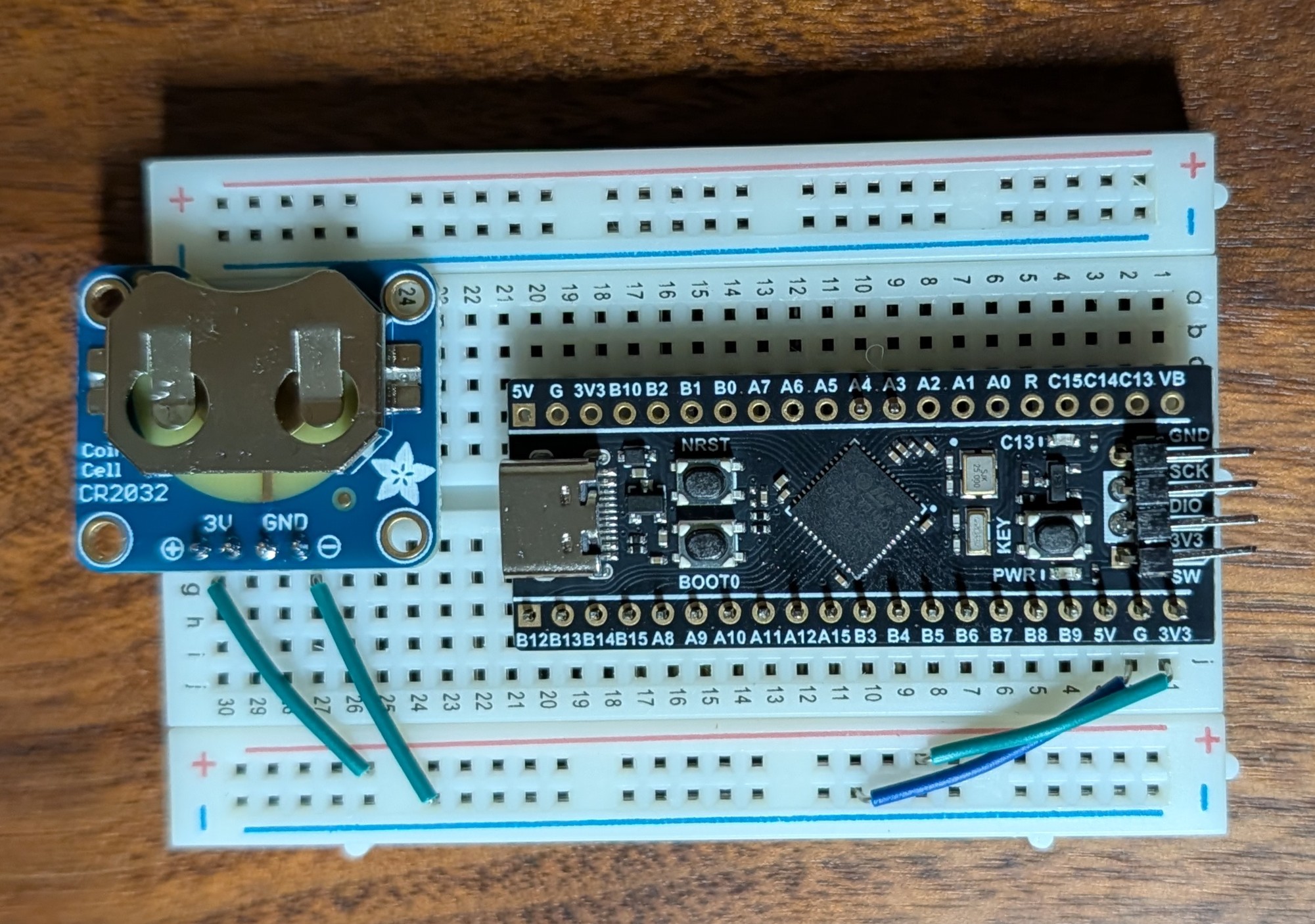
    The diagram above is the layout/wiring scheme I used for this setup. The whole configuration is powered by a USB plugged into the Blackpill. The LCD required 5v and can be driven via the 5v header on the Blackpill. One important thing to note is the the SDA and SCL pins for the i2c connection need to have pull up resistors. I connected these resistors to the 5v line from the Blackpill. I didn’t know this at first and all I could do was power on the LCD. I couldn’t get any communication without the pull up resistors, not even the i2c address. All I had on hand at the time were a 22kOhm and a 10kOhm resistor so they are what I used. These are a lot larger than most people use but they worked for me in a pinch. I would used a 4.7kOhm or similar if I were to redo this design.

    Conclusion

    I enjoyed doing this project. Getting to work with the LCD and working with the i2c driver taught me a lot about how to work with the STM32 and how the coding works. I am by no means an expert of using a STM32 but getting to work with buffers and creating the majority of this code my self was fun. It was neat to learn the snprintf and strcmp functions which I had no experience with before this. It was also a good learning experience when I had to figure out how to refresh the LCD without refreshing the whole thing. The final goal I have for working with the RTC on the STM32 is to calibrate/discipline it with me 9483 NetClock in my rack. Once I have that finished I will make a small housing to turn it into a standard desk clock with PPS accuracy…at least that’s the theory.

  • Display Time on the Blackpill using UART

    Display Time on the Blackpill using UART

    Goal

    My goal for this project was to display the RTC timer from my STM32 to my computer via Putty. Nothing fancy, just displaying the time. Accuracy is not critical for this so the internal oscillator is fine. My final goal is to have a RTC timer running on a STM32 and have it sync via the PPS from my Spectracom Netclock. But before we run I need to learn how to crawl. I’m using this as the opportunity to learn how to interact and retrieve RTC then send it visually through a serial port. The process I followed in this post is based on a tutorial I found on YouTube linked here. I found this channel very helpful for putting things in simple terms and keeping configurations simple. I highly recommend for anyone trying to learn how to use an STM32.

    Configured Pins for USART Connections

    STM32CubeMX Configuration

    The first thing I had to do was start a project is STM32CubeMX. I opened a new project and chose my board (STM32F411CEUx6.) This opens a generic base configuration with nothing selected. The first thing I needed to enable was RTC of course. I was able to set this in in the RTC section listed under Timers. The settings pictured below are all that need to be set.

    RTC Configuration Settings

    The next thing to be configured is the UART connection. This is needed so that you are actually able to interface with the computer and view the time in Putty. To configure this I used USART2 in the “Connectivity” section. All I had to change in this section was setting the mode to Asynchronous and not the Baud rate which is 115200. This will be needed later on.

    UART Configuration Settings

    Once configured the pins PA2 and PA3 both turned green and were labeled Rx and Tx respectively. These correspond to the two GPIO headers I needed to connected to. (A2,A3) After this I was able to save my project and generate code.

    Code Generation

    Now that the code is generated I actually need to configure it so that the STM knows what I want it to do. Currently its just enable functions to put it simply.

    The first section I modified was for User Includes. This Include will import the stdio C library which is used later for snprintf to convert binary to a string.

    /* USER CODE BEGIN Includes */
    #include <stdio.h>
    /* USER CODE END Includes */

    Next I added the character buffer as a User private variable. This where the strings will be stored once they are generated.

    /* USER CODE BEGIN PV */
    char buffer[100];  // Buffer to hold time and date strings
    /* USER CODE END PV */

    To make the code cleaner and easier to read the sDate and sTime variables and synced them to their respective functions.

    /* USER CODE BEGIN 2 */
    RTC_TimeTypeDef sTime;
    RTC_DateTypeDef sDate;
    /* USER CODE END 2 */

    The final step is the while loop setup. This is where the meat and potatoes happen. The first part of the while loop calls to RTC to get the time and date. These are used to add values to sTime and sDate. At this point they are stored in binary. Snprintf is then called so that we can format our binary strings into readable text and format them the way we want. Now that the string has been manipulated from binary to a formatted string its ready to be transmitted. That is where the final HAL function comes in. It takes all of our information and puts it together and sends it. This is what shows in Putty. It gets updated once per second thanks to the HAL_Delay

    /* USER CODE BEGIN WHILE */
      while (1)
      {
        /* USER CODE END WHILE */
    
    /* USER CODE BEGIN 3 */
      // Get the current time and date from RTC
      HAL_RTC_GetTime(&hrtc, &sTime, RTC_FORMAT_BIN);
      HAL_RTC_GetDate(&hrtc, &sDate, RTC_FORMAT_BIN);
    
      // Format time and date into a string
      snprintf(buffer, sizeof(buffer), "Time: %02d:%02d:%02d, Date: %02d-%02d-%02d\r\n",
               sTime.Hours, sTime.Minutes, sTime.Seconds,
               sDate.Date, sDate.Month, sDate.Year + 2000);
    
      // Transmit the formatted string over USART
      HAL_UART_Transmit(&huart2, (uint8_t*)buffer, strlen(buffer), HAL_MAX_DELAY);
    
      HAL_Delay(1000);  // Update every second
      }
      /* USER CODE END 3 */
    View Full Code Here
    /* USER CODE BEGIN Header */
    /**
      ******************************************************************************
      * @file           : main.c
      * @brief          : Main program body
      ******************************************************************************
      * @attention
      *
      * Copyright (c) 2025 STMicroelectronics.
      * All rights reserved.
      *
      * This software is licensed under terms that can be found in the LICENSE file
      * in the root directory of this software component.
      * If no LICENSE file comes with this software, it is provided AS-IS.
      *
      ******************************************************************************
      */
    /* USER CODE END Header */
    /* Includes ------------------------------------------------------------------*/
    #include "main.h"
    
    /* Private includes ----------------------------------------------------------*/
    /* USER CODE BEGIN Includes */
    #include <stdio.h>
    /* USER CODE END Includes */
    
    /* Private typedef -----------------------------------------------------------*/
    /* USER CODE BEGIN PTD */
    
    /* USER CODE END PTD */
    
    /* Private define ------------------------------------------------------------*/
    /* USER CODE BEGIN PD */
    
    /* USER CODE END PD */
    
    /* Private macro -------------------------------------------------------------*/
    /* USER CODE BEGIN PM */
    
    /* USER CODE END PM */
    
    /* Private variables ---------------------------------------------------------*/
    RTC_HandleTypeDef hrtc;
    
    UART_HandleTypeDef huart2;
    
    /* USER CODE BEGIN PV */
    char buffer[100];  // Buffer to hold time and date strings
    /* USER CODE END PV */
    
    /* Private function prototypes -----------------------------------------------*/
    void SystemClock_Config(void);
    static void MX_GPIO_Init(void);
    static void MX_RTC_Init(void);
    static void MX_USART2_UART_Init(void);
    /* USER CODE BEGIN PFP */
    
    /* USER CODE END PFP */
    
    /* Private user code ---------------------------------------------------------*/
    /* USER CODE BEGIN 0 */
    
    /* USER CODE END 0 */
    
    /**
      * @brief  The application entry point.
      * @retval int
      */
    int main(void)
    {
    
      /* USER CODE BEGIN 1 */
    
      /* USER CODE END 1 */
    
      /* MCU Configuration--------------------------------------------------------*/
    
      /* Reset of all peripherals, Initializes the Flash interface and the Systick. */
      HAL_Init();
    
      /* USER CODE BEGIN Init */
    
      /* USER CODE END Init */
    
      /* Configure the system clock */
      SystemClock_Config();
    
      /* USER CODE BEGIN SysInit */
    
      /* USER CODE END SysInit */
    
      /* Initialize all configured peripherals */
      MX_GPIO_Init();
      MX_RTC_Init();
      MX_USART2_UART_Init();
      /* USER CODE BEGIN 2 */
      RTC_TimeTypeDef sTime;
      RTC_DateTypeDef sDate;
      /* USER CODE END 2 */
    
      /* Infinite loop */
      /* USER CODE BEGIN WHILE */
      while (1)
      {
        /* USER CODE END WHILE */
    
        /* USER CODE BEGIN 3 */
    	  // Get the current time and date from RTC
    	  HAL_RTC_GetTime(&hrtc, &sTime, RTC_FORMAT_BIN);
    	  HAL_RTC_GetDate(&hrtc, &sDate, RTC_FORMAT_BIN);
    
    	  // Format time and date into a string
    	  snprintf(buffer, sizeof(buffer), "Time: %02d:%02d:%02d, Date: %02d-%02d-%02d\r\n",
    	           sTime.Hours, sTime.Minutes, sTime.Seconds,
    	           sDate.Date, sDate.Month, sDate.Year + 2000);
    
    	  // Transmit the formatted string over USART
    	  HAL_UART_Transmit(&huart2, (uint8_t*)buffer, strlen(buffer), HAL_MAX_DELAY);
    
    	  HAL_Delay(1000);  // Update every second
      }
      /* USER CODE END 3 */
    }
    
    /**
      * @brief System Clock Configuration
      * @retval None
      */
    void SystemClock_Config(void)
    {
      RCC_OscInitTypeDef RCC_OscInitStruct = {0};
      RCC_ClkInitTypeDef RCC_ClkInitStruct = {0};
    
      /** Configure the main internal regulator output voltage
      */
      __HAL_RCC_PWR_CLK_ENABLE();
      __HAL_PWR_VOLTAGESCALING_CONFIG(PWR_REGULATOR_VOLTAGE_SCALE1);
    
      /** Initializes the RCC Oscillators according to the specified parameters
      * in the RCC_OscInitTypeDef structure.
      */
      RCC_OscInitStruct.OscillatorType = RCC_OSCILLATORTYPE_HSI|RCC_OSCILLATORTYPE_LSI;
      RCC_OscInitStruct.HSIState = RCC_HSI_ON;
      RCC_OscInitStruct.HSICalibrationValue = RCC_HSICALIBRATION_DEFAULT;
      RCC_OscInitStruct.LSIState = RCC_LSI_ON;
      RCC_OscInitStruct.PLL.PLLState = RCC_PLL_NONE;
      if (HAL_RCC_OscConfig(&RCC_OscInitStruct) != HAL_OK)
      {
        Error_Handler();
      }
    
      /** Initializes the CPU, AHB and APB buses clocks
      */
      RCC_ClkInitStruct.ClockType = RCC_CLOCKTYPE_HCLK|RCC_CLOCKTYPE_SYSCLK
                                  |RCC_CLOCKTYPE_PCLK1|RCC_CLOCKTYPE_PCLK2;
      RCC_ClkInitStruct.SYSCLKSource = RCC_SYSCLKSOURCE_HSI;
      RCC_ClkInitStruct.AHBCLKDivider = RCC_SYSCLK_DIV1;
      RCC_ClkInitStruct.APB1CLKDivider = RCC_HCLK_DIV1;
      RCC_ClkInitStruct.APB2CLKDivider = RCC_HCLK_DIV1;
    
      if (HAL_RCC_ClockConfig(&RCC_ClkInitStruct, FLASH_LATENCY_0) != HAL_OK)
      {
        Error_Handler();
      }
    }
    
    /**
      * @brief RTC Initialization Function
      * @param None
      * @retval None
      */
    static void MX_RTC_Init(void)
    {
    
      /* USER CODE BEGIN RTC_Init 0 */
    
      /* USER CODE END RTC_Init 0 */
    
      RTC_TimeTypeDef sTime = {0};
      RTC_DateTypeDef sDate = {0};
    
      /* USER CODE BEGIN RTC_Init 1 */
    
      /* USER CODE END RTC_Init 1 */
    
      /** Initialize RTC Only
      */
      hrtc.Instance = RTC;
      hrtc.Init.HourFormat = RTC_HOURFORMAT_24;
      hrtc.Init.AsynchPrediv = 127;
      hrtc.Init.SynchPrediv = 255;
      hrtc.Init.OutPut = RTC_OUTPUT_DISABLE;
      hrtc.Init.OutPutPolarity = RTC_OUTPUT_POLARITY_HIGH;
      hrtc.Init.OutPutType = RTC_OUTPUT_TYPE_OPENDRAIN;
      if (HAL_RTC_Init(&hrtc) != HAL_OK)
      {
        Error_Handler();
      }
    
      /* USER CODE BEGIN Check_RTC_BKUP */
    
      /* USER CODE END Check_RTC_BKUP */
    
      /** Initialize RTC and set the Time and Date
      */
      sTime.Hours = 12;
      sTime.Minutes = 30;
      sTime.Seconds = 0;
      sTime.DayLightSaving = RTC_DAYLIGHTSAVING_NONE;
      sTime.StoreOperation = RTC_STOREOPERATION_RESET;
      if (HAL_RTC_SetTime(&hrtc, &sTime, RTC_FORMAT_BIN) != HAL_OK)
      {
        Error_Handler();
      }
      sDate.WeekDay = RTC_WEEKDAY_MONDAY;
      sDate.Month = RTC_MONTH_NOVEMBER;
      sDate.Date = 10;
      sDate.Year = 25;
    
      if (HAL_RTC_SetDate(&hrtc, &sDate, RTC_FORMAT_BIN) != HAL_OK)
      {
        Error_Handler();
      }
      /* USER CODE BEGIN RTC_Init 2 */
    
      /* USER CODE END RTC_Init 2 */
    
    }
    
    /**
      * @brief USART2 Initialization Function
      * @param None
      * @retval None
      */
    static void MX_USART2_UART_Init(void)
    {
    
      /* USER CODE BEGIN USART2_Init 0 */
    
      /* USER CODE END USART2_Init 0 */
    
      /* USER CODE BEGIN USART2_Init 1 */
    
      /* USER CODE END USART2_Init 1 */
      huart2.Instance = USART2;
      huart2.Init.BaudRate = 115200;
      huart2.Init.WordLength = UART_WORDLENGTH_8B;
      huart2.Init.StopBits = UART_STOPBITS_1;
      huart2.Init.Parity = UART_PARITY_NONE;
      huart2.Init.Mode = UART_MODE_TX_RX;
      huart2.Init.HwFlowCtl = UART_HWCONTROL_NONE;
      huart2.Init.OverSampling = UART_OVERSAMPLING_16;
      if (HAL_UART_Init(&huart2) != HAL_OK)
      {
        Error_Handler();
      }
      /* USER CODE BEGIN USART2_Init 2 */
    
      /* USER CODE END USART2_Init 2 */
    
    }
    
    /**
      * @brief GPIO Initialization Function
      * @param None
      * @retval None
      */
    static void MX_GPIO_Init(void)
    {
      /* USER CODE BEGIN MX_GPIO_Init_1 */
    
      /* USER CODE END MX_GPIO_Init_1 */
    
      /* GPIO Ports Clock Enable */
      __HAL_RCC_GPIOA_CLK_ENABLE();
    
      /* USER CODE BEGIN MX_GPIO_Init_2 */
    
      /* USER CODE END MX_GPIO_Init_2 */
    }
    
    /* USER CODE BEGIN 4 */
    
    /* USER CODE END 4 */
    
    /**
      * @brief  This function is executed in case of error occurrence.
      * @retval None
      */
    void Error_Handler(void)
    {
      /* USER CODE BEGIN Error_Handler_Debug */
      /* User can add his own implementation to report the HAL error return state */
      __disable_irq();
      while (1)
      {
      }
      /* USER CODE END Error_Handler_Debug */
    }
    #ifdef USE_FULL_ASSERT
    /**
      * @brief  Reports the name of the source file and the source line number
      *         where the assert_param error has occurred.
      * @param  file: pointer to the source file name
      * @param  line: assert_param error line source number
      * @retval None
      */
    void assert_failed(uint8_t *file, uint32_t line)
    {
      /* USER CODE BEGIN 6 */
      /* User can add his own implementation to report the file name and line number,
         ex: printf("Wrong parameters value: file %s on line %d\r\n", file, line) */
      /* USER CODE END 6 */
    }
    #endif /* USE_FULL_ASSERT */
    Code Source

    CircuitGatorHQ Github Post

    Wiring

    The wiring was pretty simple to do. I just need to supply power to the MCU and connect to the UART pins. I also added a small CR2032 battery chip so that it can be unplugged and still powered to keep time.

    Conclusion

    I had a lot of fun getting this figured out. It helped teach me the basics of how the code works for STM32. It also showed me how to deal with RTC and getting the information from binary and then send that information to a buffer with snprintf. This project is also going to be used as the base for a future project where I use the Blackpill to display time and date with i2c to an LCD.

  • Modernized IBM Model M with Cherry Switches

    Modernized IBM Model M with Cherry Switches

    Introduction

    Over the past few years I’ve become interested in tinkering with keyboards. I have a Keychron Q1 Pro and K10 that are customized with new paint and switches etc… But a I’ve always dreamed of building a Model M keyboard with modern mechanical switches. They look so good! I can appreciated the feel and sound of the Model M, but its just not practical for office use. Its far too loud. So began the project of trying to make a custom PCB to swap into a donor Model M. I quickly found that I do not have the expertise to design such a project from scratch. But while I was pursuing Google Images I found a GitHub post from Dcpedit. (Link) Dcpedit had made a repository that had everything I was looking for. They documented the entire process and there was very little for me left to figure out once the time came to start ordering and assembling.

    Gathering Supplies

    The table below outlines all of the parts I purchased along with their part numbers where applicable. I attached a rough price estimate at the time of order. Most of the prices are probably pretty stable but the order from JLCPCB was affected by tariffs making it substantially more expensive. I also bought extra of some parts because I was unsure how hard it was going to be to solder since I’m a novice at best. So you could probably cut some corners as well.

    Digikey Order (~$52 USD)

    3x 30pin FCC Connector – OR1179CT
    1x 30pin FCC Cable – WM19610
    3x Green 3mm LED – 732-5008
    3x Clear 3mm LED – 365-1467
    3x 470ohm Resistor – CF18JT470RCT
    3x 10kOhm Resistor – CF14JT10K0CT
    1x 22kOhm Resistor – CF14JT22K0CT
    65x BAV70 Didoes – 1727-2912-1
    1x BlackPill STM32F411 – 1738-DFR0864 (Includes 2x headers)
    6x Kailh Switch Sockets – 1528-4958 (Packs of 20x)

    Amazon(~$36 USD)

    60x M2.5x4mm+6mm Standoff screws – Link (4mm instead of 6mm may be helpful. These had to be ground down to fit)
    1x DUROCK V3 Stabilizers –Link
    60x m2.5×4 Button Screws – Link

    JLCPCB Order (~$115)

    5x 1.2mm FR4 Main board
    5x 1.6mm FR4 Daughter board


    Ebay (~$130)

    IBM Model M donor Keyboard

    PCB Assembly

    The assembly of the PCB’s were pretty self explanatory. I think the most important thing is to pay attention and take it slow. I made a few mistakes during the solder process that could have been avoided if I took more time. The soldering its self was not very difficult. The hardest part in my opinion were the diodes followed by the ribbon cable connector. I think anyone with a decent understanding of how soldering works could do this. My previous experience was soldering USB cables and not much else.

    Tools Required

    • Good Quality Soldering Iron
    • Brass sponge for tip cleaning
    • Flux
    • Lead based solder
    • Solder wick (especially helpful for 30pin)

    Step 1: Solder the Daughter board

    I first began by soldering the daughter board. For this I started by first soldering the 4 pin header to the BlackPill. Once that was complete I mounted the 2 30pin headers to the PCB and soldered then into place. Once those were held at the base I soldered the 4pin head as well to affix the Blackpill. Once it was held in place I was able to solder the rest of the pins on the top of the pill as well. Soldering the headers like this makes it non removable incase you wanted to reuse this module in the future without de soldering.

    Once the module was soldered I moved over to the 30pin. I started by first getting solder on the pads then attaching the two support pins on either end. Make sure to keep the data pins aligned with there respective pads while doing this. I was able to spread solder to each pad/pin without much issue but I did cross a few pins. This is where it came in handy to have soldering wick available.

    Once both of these components have been soldered I connected the ribbon cable and used it to test conductivity to make sure each pin could reach the BlackPill. They all passed first try thankfully! Note the first and last pin are grounds. The pin on the far right also grounds to the PCB so it can’t be traced. You can refer the the schematic in KiCad to see this if needed.

    Step 2: Solder the main PCB

    Soldering the main board was a similar process to the daughter board. I started by pre-soldering all of the pads. Once that was complete I did all of the switch sockets. They were pretty quick to do, the only thing to make sure you get correct is the orientation. I had a few issues with this, if you get them upside down they will block the stems of your switches. Once the sockets were all on I soldered the diodes followed by the 30pin, transistors and LED’s. These were all relatively easy, although the size of the diodes made them a bit difficult at times.

    One important thing to note would be to pre bend the main PCB for 24hrs or so before soldering. I didn’t do this step and it caused me a few issues. During initial assembly I had three or four diodes break at the solder joint.

    Step 3: Disassemble the Model M donor

    Next was to disassemble the Model M. Once you unscrew the back and get the cover off you should see the keys and the plate they are mounted too. You should be able to carefully detach the ribbons and pull it out. Once removed you will need to use a razor to ‘cut’ the black supports that are cast through the metal back plate. Once they are all cut you should be able to carefully remove the capacities sheets/key assemblies. They are no longer retained at this point so the keys will want to fall out if your not careful. Once that is all done you are able to remove the main controller.

    Step4: Attaching the stabilizers

    At this point you are able to attach the stabilizers to the PCB. I chose to use screw mount stabs because of issues I had using surface mount stabs in the past. Because these require screwing from the back you have to do it before you attach it to the back plate. These are pretty straightforward to mount and the Durock V3 stabs worked great for me. They mounted to the pre drilled stab holes without issue.

    Step 5: Attach the PCB to the back plate

    To attach the PCB to the back plate I used brass standoffs. I used 4mm deep standoffs with a 6mm base to push through the plate. In hind sight I think 4mm for the base would have been better because I did have to grind some of them down towards the bottom where the space bar is located. I didn’t put too much thought into placement. I basically just stuck them anywhere there was a stock hole. The PCB design has screw mount holes in a bout 90% of the stock screw locations which in my opinion is more that enough support.

    Once the standoffs were attached I was able to mount the PCB. To try and limit stress I would start at the F row and work my way down slowly. I tried to keep the bend even across the board and avoid introducing too much bend all at once. I did have to re mount the PCB once because of a few bad joints on the diodes. The solder didn’t hold up to the bend and had to be re flowed. I strongly recommend testing the PCB with switches before mounting. It does add extra work but it will save headache in the future. Remounting the PCB for one broken switch is no fun, trust me.

    Step 6: Switches and Key caps

    This step was my favorite because you could finally see the keyboard start to take its final form. This step is pretty similar most mechanical keyboards, you just need to insert the switches in there respective places and then install the key caps.

    I did run into a few quirks during this step. I had a pin issue with two switch mounts and a short from the switch. The short from the switch was a simple fix. The pin was poking too far down and was shorting to the back plate. To fix this I just trimmed the pin so its shorter and it stopped giving issues. The switch mounts were are bit harder to figure out but the fix was simple. The teeth that bite the pins of the switch when inserted were lose. To fix it I just used a needle and bent the switch teeth so they bit the pin better.

    Step 7: Flashing the firmware

    To flash the firmware I used QMK Toolbox. I tried using the web tool to create my own firmware but was having issues. The PCB layout for the mmmModel M is no longer listed and I didn’t want to go through the hassle of adding it or finding another one that is compatible.

    How to Flash the Blackpill:

    1. Open QMK and plug in the controller
    2. Place the controller into flash mode by holding Boot0, then press RESET and release Boot0
      • If done properly the Software will acknowledge it on screen.
    3. Leave the settings in QMK as they are and open the .bin file located in "%Directory%\mod-mmm-master\firmware\blackpill\dcpedit_modmmm_standard_via.bin"
    4. Click “Flash” and it should succeed. You are then safe to unplug the controller.

    Step 8: Final Assembly

    Now they the Controller is flashed you can do the final assembly. Since the key switches are already mounted to the black plate this step is pretty straightforward. I just had the place the controller into the case and then place the plate over top. Once that was in I could plug in the 30 pin ribbon cable. I did have issues with the Controller PCB being lose so I taped it down with electrical tape. From there I was able to screw it together. After that it was finally ready to plug in and be used!

    Sound Test:

    Here is a short sounds test of it completed for those who are curious.

    Conclusion:

    I had a lot of fun doing this project. It taught me a lot. Even though I did not create the PCB design, I learned a lot from assembling it. I was able to practice my soldering and solder parts that for me are quite small. It also helped with my understanding of how a keyboard actually works under the hood which was cool. They are simple but when you see one online you always think they would be so complex if you wanted to make your own. But in reality they are not as complicated as you think. Of course if you make you own PCB its considerably harder, but there are a lot of 3rd party PCB’s posted and sold they you could use instead of making your own.

    The performance and reliability of this keyboard has been good as well. Once completed I haven’t had any issues and its worked great. I’ve been using it daily for the last few week to play games and even write this article.

    I would definitely consider building something like this again.

  • Selfhosted GPS NTP – Spectracom Netclock 9483

    Selfhosted GPS NTP – Spectracom Netclock 9483

    Introduction

    While working in one of the datacenters at my organization I come across many interesting pieces of enterprise hardware. Most of which I couldn’t dream of running at home due to noise and of course, I don’t own a power station. But one server in particular that caught my interest was a Netclock 9483 managed by one of our vendors. Immediately it drew my attention. I knew that one day I had to have one of my own. Their is no practical reason for this other that I genuinely like the look that it gives my rack. Plus what who doesn’t want to brag about having your own private sub ~100ns time source.

    Acquiring Hardware

    Sadly, we wont be decommissioning our Netclock anytime soon, so I had to find the next best source, eBay! I kept my eye out for a few weeks, my goal was to get one is good operable condition with a OCXO for around $250USD or less. At the time of searching most fully functional 9483s were listed for $800USD+. I didn’t want to spend this much so I kept researching and came across a listing for $400, only issue was the LED display was noted as faulty, otherwise it would boot and was in physically good condition. Because of the issues I sent a lowball offer of $200. The seller immediately accepted. In hindsight it makes me wish I sent an even lower offer but alas I did not. The seller was Canadian and the shipping went smooth. FedEx hung up the tracking for a while due to weather but eventually it arrived with no damage.

    Internal picture after delivery while looking over the hardware

    First Boot!

    Now came the time for first boot. Before attempting to boot I did a look over the hardware to check for any obvious issues or missing components. Everything looked pretty normal to me although I noticed a suspicious Compact Flash slot that would later come to haunt me. Once satisfied I plugged it in, flipped the switch and crossed my fingers. Immediately the fan bearing started grinding, thankfully not a big deal. After about 5s the front LED panel powered up. The display was blank but the backlight turned on. Then the time display on the side powered up and began to count up. At this point I was hopeful that the device was “on” and that the LED display was blank like the eBay listing said.

    Troubleshooting

    Once I booted it up I let the clock idle for a few minutes and nothing changed. I figured that since the screen indeed was blank I should move onto accessing the web GUI. Needless to say that came with its own issues. I plugged it into my 3560X switch and waited a bit for the activity lights to go green. Once green I connected to my Omada GUI and checked DHCP for what reservation it picked up. This turned up nothing, I couldn’t find the IP. I tried checked the IP table on the switch to no avail as well. At this point I became very skeptical of the CF slot being empty but figured I would give it one more go to get the IP. I plugged it into my spare laptop while running a PCAP to see if I could find a ARP advertisement to get the IP…nothing, time to start Googling!

    This is where I ran across a old forum post from someone in a similar situation in 2021. (Located here) They were having similar issues although they bricked the BIOS. Not sure if they were ever able to get it fixed but the information they shared was enough to convince me the CF slot indeed was where a OS would be installed. This makes sense in hindsight since these devices are marketed to law enforcement. They must have removed it before recycling the device. Now I had to source a useable image to flash. Luckily the stars aligned and someone posted multiple different images for a 9483 on archive.org! With this .img I was able to use rufus and flash the image easily.

    Now for the moment of truth…Its alive!

    Picture of first boot

    I was ecstatic, the LED display was functional! The eBay listing was incorrect and the screen was functional as you can see above. The only fault is the lower dot on the colon for the 9 digit display but I will save that for a future project. Once plugged in it pulled an IP and displayed it on the front panel. With this I was able to access the GUI and login with the default credentials. Whew after some of the other reading I was doing I was worried that I was going to finally get the .img to work just to get smacked with a license prompt and be out of luck.

    GPS Configuration

    Now that I was able to get in the GUI and everything looked to be functional it was finally time to get it setup and running. This overall was pretty simple. My goal is to setup the antenna and successfully pull GPS time and have NTP backup references if needed. For my antenna I didn’t get anything fancy, I went with a Bingfu SMA antenna from Amazon and a type N to SMA adapter. I’m keeping an eye out for a Spectracom 8230 to popup on eBay to complete the ‘official’ setup but for now a Bingfu works.

    Parts List:

    Once installed the Netclock automatically acknowledged the antenna and began a satellite survey. This took a few tries to get right, but once I got the antenna placed in a good spot where it would get signal it took about 3hours. After the survey it automatically pulled time and started ticking. The time was a bit off in the beginning, but after adjusting a few settings I got it to keep consistent time. Currently it is able to keep an estimated time error(ETE) of 10ns < ETE <= 100ns. I can now say that I maintain my own stratum 1 time server, time to check that off the bucket list.

    GPS Disciplined Desktop Clock?

    I hope in the future to use this for more than just a rack decoration and simple time keeping. Currently I only have 2 clients referencing it. (My Desktop and my home server) Since it has a 1PPS output I want to try and build a clock that will run using that signal to maintain time. So instead of running a 555 clock circuit or something similar it will work off the raw PPS signal for when to increment the time. Is this possible, I have no idea but it sounds like a fun project!

    Hope you found this interesting, thanks for reading!