Goal
My goal for this project was to display the RTC timer from my STM32 to my computer via Putty. Nothing fancy, just displaying the time. Accuracy is not critical for this so the internal oscillator is fine. My final goal is to have a RTC timer running on a STM32 and have it sync via the PPS from my Spectracom Netclock. But before we run I need to learn how to crawl. I’m using this as the opportunity to learn how to interact and retrieve RTC then send it visually through a serial port. The process I followed in this post is based on a tutorial I found on YouTube linked here. I found this channel very helpful for putting things in simple terms and keeping configurations simple. I highly recommend for anyone trying to learn how to use an STM32.

STM32CubeMX Configuration
The first thing I had to do was start a project is STM32CubeMX. I opened a new project and chose my board (STM32F411CEUx6.) This opens a generic base configuration with nothing selected. The first thing I needed to enable was RTC of course. I was able to set this in in the RTC section listed under Timers. The settings pictured below are all that need to be set.

The next thing to be configured is the UART connection. This is needed so that you are actually able to interface with the computer and view the time in Putty. To configure this I used USART2 in the “Connectivity” section. All I had to change in this section was setting the mode to Asynchronous and not the Baud rate which is 115200. This will be needed later on.

Once configured the pins PA2 and PA3 both turned green and were labeled Rx and Tx respectively. These correspond to the two GPIO headers I needed to connected to. (A2,A3) After this I was able to save my project and generate code.
Code Generation
Now that the code is generated I actually need to configure it so that the STM knows what I want it to do. Currently its just enable functions to put it simply.
The first section I modified was for User Includes. This Include will import the stdio C library which is used later for snprintf to convert binary to a string.
/* USER CODE BEGIN Includes */
#include <stdio.h>
/* USER CODE END Includes */
Next I added the character buffer as a User private variable. This where the strings will be stored once they are generated.
/* USER CODE BEGIN PV */
char buffer[100];  // Buffer to hold time and date strings
/* USER CODE END PV */
To make the code cleaner and easier to read the sDate and sTime variables and synced them to their respective functions.
/* USER CODE BEGIN 2 */
RTC_TimeTypeDef sTime;
RTC_DateTypeDef sDate;
/* USER CODE END 2 */
The final step is the while loop setup. This is where the meat and potatoes happen. The first part of the while loop calls to RTC to get the time and date. These are used to add values to sTime and sDate. At this point they are stored in binary. Snprintf is then called so that we can format our binary strings into readable text and format them the way we want. Now that the string has been manipulated from binary to a formatted string its ready to be transmitted. That is where the final HAL function comes in. It takes all of our information and puts it together and sends it. This is what shows in Putty. It gets updated once per second thanks to the HAL_Delay
/* USER CODE BEGIN WHILE */
  while (1)
  {
    /* USER CODE END WHILE */

/* USER CODE BEGIN 3 */
  // Get the current time and date from RTC
  HAL_RTC_GetTime(&hrtc, &sTime, RTC_FORMAT_BIN);
  HAL_RTC_GetDate(&hrtc, &sDate, RTC_FORMAT_BIN);

  // Format time and date into a string
  snprintf(buffer, sizeof(buffer), "Time: %02d:%02d:%02d, Date: %02d-%02d-%02d\r\n",
           sTime.Hours, sTime.Minutes, sTime.Seconds,
           sDate.Date, sDate.Month, sDate.Year + 2000);

  // Transmit the formatted string over USART
  HAL_UART_Transmit(&huart2, (uint8_t*)buffer, strlen(buffer), HAL_MAX_DELAY);

  HAL_Delay(1000);  // Update every second
  }
  /* USER CODE END 3 */
View Full Code Here
/* USER CODE BEGIN Header */
/**
  ******************************************************************************
  * @file           : main.c
  * @brief          : Main program body
  ******************************************************************************
  * @attention
  *
  * Copyright (c) 2025 STMicroelectronics.
  * All rights reserved.
  *
  * This software is licensed under terms that can be found in the LICENSE file
  * in the root directory of this software component.
  * If no LICENSE file comes with this software, it is provided AS-IS.
  *
  ******************************************************************************
  */
/* USER CODE END Header */
/* Includes ------------------------------------------------------------------*/
#include "main.h"

/* Private includes ----------------------------------------------------------*/
/* USER CODE BEGIN Includes */
#include <stdio.h>
/* USER CODE END Includes */

/* Private typedef -----------------------------------------------------------*/
/* USER CODE BEGIN PTD */

/* USER CODE END PTD */

/* Private define ------------------------------------------------------------*/
/* USER CODE BEGIN PD */

/* USER CODE END PD */

/* Private macro -------------------------------------------------------------*/
/* USER CODE BEGIN PM */

/* USER CODE END PM */

/* Private variables ---------------------------------------------------------*/
RTC_HandleTypeDef hrtc;

UART_HandleTypeDef huart2;

/* USER CODE BEGIN PV */
char buffer[100];  // Buffer to hold time and date strings
/* USER CODE END PV */

/* Private function prototypes -----------------------------------------------*/
void SystemClock_Config(void);
static void MX_GPIO_Init(void);
static void MX_RTC_Init(void);
static void MX_USART2_UART_Init(void);
/* USER CODE BEGIN PFP */

/* USER CODE END PFP */

/* Private user code ---------------------------------------------------------*/
/* USER CODE BEGIN 0 */

/* USER CODE END 0 */

/**
  * @brief  The application entry point.
  * @retval int
  */
int main(void)
{

  /* USER CODE BEGIN 1 */

  /* USER CODE END 1 */

  /* MCU Configuration--------------------------------------------------------*/

  /* Reset of all peripherals, Initializes the Flash interface and the Systick. */
  HAL_Init();

  /* USER CODE BEGIN Init */

  /* USER CODE END Init */

  /* Configure the system clock */
  SystemClock_Config();

  /* USER CODE BEGIN SysInit */

  /* USER CODE END SysInit */

  /* Initialize all configured peripherals */
  MX_GPIO_Init();
  MX_RTC_Init();
  MX_USART2_UART_Init();
  /* USER CODE BEGIN 2 */
  RTC_TimeTypeDef sTime;
  RTC_DateTypeDef sDate;
  /* USER CODE END 2 */

  /* Infinite loop */
  /* USER CODE BEGIN WHILE */
  while (1)
  {
    /* USER CODE END WHILE */

    /* USER CODE BEGIN 3 */
	  // Get the current time and date from RTC
	  HAL_RTC_GetTime(&hrtc, &sTime, RTC_FORMAT_BIN);
	  HAL_RTC_GetDate(&hrtc, &sDate, RTC_FORMAT_BIN);

	  // Format time and date into a string
	  snprintf(buffer, sizeof(buffer), "Time: %02d:%02d:%02d, Date: %02d-%02d-%02d\r\n",
	           sTime.Hours, sTime.Minutes, sTime.Seconds,
	           sDate.Date, sDate.Month, sDate.Year + 2000);

	  // Transmit the formatted string over USART
	  HAL_UART_Transmit(&huart2, (uint8_t*)buffer, strlen(buffer), HAL_MAX_DELAY);

	  HAL_Delay(1000);  // Update every second
  }
  /* USER CODE END 3 */
}

/**
  * @brief System Clock Configuration
  * @retval None
  */
void SystemClock_Config(void)
{
  RCC_OscInitTypeDef RCC_OscInitStruct = {0};
  RCC_ClkInitTypeDef RCC_ClkInitStruct = {0};

  /** Configure the main internal regulator output voltage
  */
  __HAL_RCC_PWR_CLK_ENABLE();
  __HAL_PWR_VOLTAGESCALING_CONFIG(PWR_REGULATOR_VOLTAGE_SCALE1);

  /** Initializes the RCC Oscillators according to the specified parameters
  * in the RCC_OscInitTypeDef structure.
  */
  RCC_OscInitStruct.OscillatorType = RCC_OSCILLATORTYPE_HSI|RCC_OSCILLATORTYPE_LSI;
  RCC_OscInitStruct.HSIState = RCC_HSI_ON;
  RCC_OscInitStruct.HSICalibrationValue = RCC_HSICALIBRATION_DEFAULT;
  RCC_OscInitStruct.LSIState = RCC_LSI_ON;
  RCC_OscInitStruct.PLL.PLLState = RCC_PLL_NONE;
  if (HAL_RCC_OscConfig(&RCC_OscInitStruct) != HAL_OK)
  {
    Error_Handler();
  }

  /** Initializes the CPU, AHB and APB buses clocks
  */
  RCC_ClkInitStruct.ClockType = RCC_CLOCKTYPE_HCLK|RCC_CLOCKTYPE_SYSCLK
                              |RCC_CLOCKTYPE_PCLK1|RCC_CLOCKTYPE_PCLK2;
  RCC_ClkInitStruct.SYSCLKSource = RCC_SYSCLKSOURCE_HSI;
  RCC_ClkInitStruct.AHBCLKDivider = RCC_SYSCLK_DIV1;
  RCC_ClkInitStruct.APB1CLKDivider = RCC_HCLK_DIV1;
  RCC_ClkInitStruct.APB2CLKDivider = RCC_HCLK_DIV1;

  if (HAL_RCC_ClockConfig(&RCC_ClkInitStruct, FLASH_LATENCY_0) != HAL_OK)
  {
    Error_Handler();
  }
}

/**
  * @brief RTC Initialization Function
  * @param None
  * @retval None
  */
static void MX_RTC_Init(void)
{

  /* USER CODE BEGIN RTC_Init 0 */

  /* USER CODE END RTC_Init 0 */

  RTC_TimeTypeDef sTime = {0};
  RTC_DateTypeDef sDate = {0};

  /* USER CODE BEGIN RTC_Init 1 */

  /* USER CODE END RTC_Init 1 */

  /** Initialize RTC Only
  */
  hrtc.Instance = RTC;
  hrtc.Init.HourFormat = RTC_HOURFORMAT_24;
  hrtc.Init.AsynchPrediv = 127;
  hrtc.Init.SynchPrediv = 255;
  hrtc.Init.OutPut = RTC_OUTPUT_DISABLE;
  hrtc.Init.OutPutPolarity = RTC_OUTPUT_POLARITY_HIGH;
  hrtc.Init.OutPutType = RTC_OUTPUT_TYPE_OPENDRAIN;
  if (HAL_RTC_Init(&hrtc) != HAL_OK)
  {
    Error_Handler();
  }

  /* USER CODE BEGIN Check_RTC_BKUP */

  /* USER CODE END Check_RTC_BKUP */

  /** Initialize RTC and set the Time and Date
  */
  sTime.Hours = 12;
  sTime.Minutes = 30;
  sTime.Seconds = 0;
  sTime.DayLightSaving = RTC_DAYLIGHTSAVING_NONE;
  sTime.StoreOperation = RTC_STOREOPERATION_RESET;
  if (HAL_RTC_SetTime(&hrtc, &sTime, RTC_FORMAT_BIN) != HAL_OK)
  {
    Error_Handler();
  }
  sDate.WeekDay = RTC_WEEKDAY_MONDAY;
  sDate.Month = RTC_MONTH_NOVEMBER;
  sDate.Date = 10;
  sDate.Year = 25;

  if (HAL_RTC_SetDate(&hrtc, &sDate, RTC_FORMAT_BIN) != HAL_OK)
  {
    Error_Handler();
  }
  /* USER CODE BEGIN RTC_Init 2 */

  /* USER CODE END RTC_Init 2 */

}

/**
  * @brief USART2 Initialization Function
  * @param None
  * @retval None
  */
static void MX_USART2_UART_Init(void)
{

  /* USER CODE BEGIN USART2_Init 0 */

  /* USER CODE END USART2_Init 0 */

  /* USER CODE BEGIN USART2_Init 1 */

  /* USER CODE END USART2_Init 1 */
  huart2.Instance = USART2;
  huart2.Init.BaudRate = 115200;
  huart2.Init.WordLength = UART_WORDLENGTH_8B;
  huart2.Init.StopBits = UART_STOPBITS_1;
  huart2.Init.Parity = UART_PARITY_NONE;
  huart2.Init.Mode = UART_MODE_TX_RX;
  huart2.Init.HwFlowCtl = UART_HWCONTROL_NONE;
  huart2.Init.OverSampling = UART_OVERSAMPLING_16;
  if (HAL_UART_Init(&huart2) != HAL_OK)
  {
    Error_Handler();
  }
  /* USER CODE BEGIN USART2_Init 2 */

  /* USER CODE END USART2_Init 2 */

}

/**
  * @brief GPIO Initialization Function
  * @param None
  * @retval None
  */
static void MX_GPIO_Init(void)
{
  /* USER CODE BEGIN MX_GPIO_Init_1 */

  /* USER CODE END MX_GPIO_Init_1 */

  /* GPIO Ports Clock Enable */
  __HAL_RCC_GPIOA_CLK_ENABLE();

  /* USER CODE BEGIN MX_GPIO_Init_2 */

  /* USER CODE END MX_GPIO_Init_2 */
}

/* USER CODE BEGIN 4 */

/* USER CODE END 4 */

/**
  * @brief  This function is executed in case of error occurrence.
  * @retval None
  */
void Error_Handler(void)
{
  /* USER CODE BEGIN Error_Handler_Debug */
  /* User can add his own implementation to report the HAL error return state */
  __disable_irq();
  while (1)
  {
  }
  /* USER CODE END Error_Handler_Debug */
}
#ifdef USE_FULL_ASSERT
/**
  * @brief  Reports the name of the source file and the source line number
  *         where the assert_param error has occurred.
  * @param  file: pointer to the source file name
  * @param  line: assert_param error line source number
  * @retval None
  */
void assert_failed(uint8_t *file, uint32_t line)
{
  /* USER CODE BEGIN 6 */
  /* User can add his own implementation to report the file name and line number,
     ex: printf("Wrong parameters value: file %s on line %d\r\n", file, line) */
  /* USER CODE END 6 */
}
#endif /* USE_FULL_ASSERT */
Code Source
Wiring
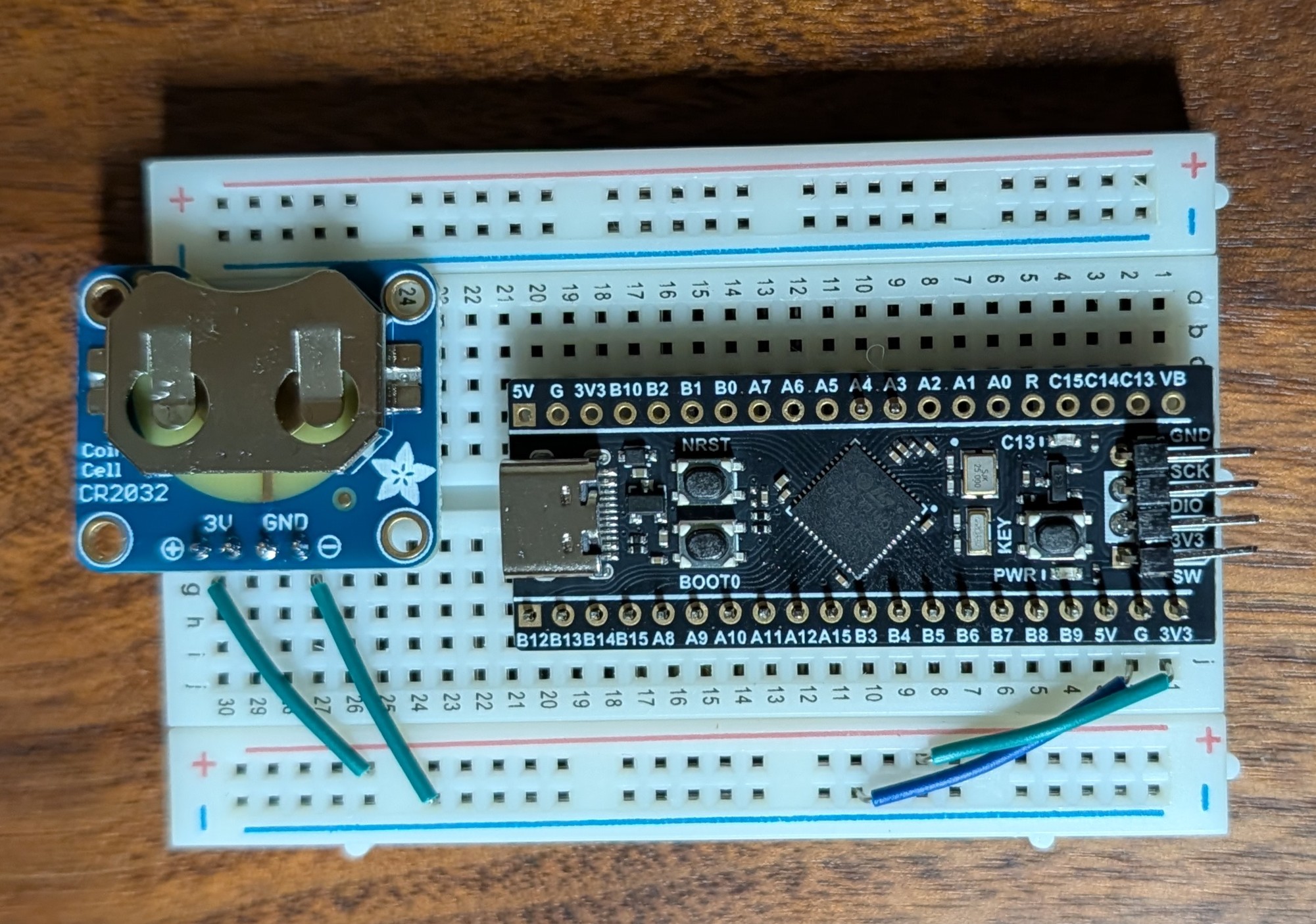
The wiring was pretty simple to do. I just need to supply power to the MCU and connect to the UART pins. I also added a small CR2032 battery chip so that it can be unplugged and still powered to keep time.

Conclusion
I had a lot of fun getting this figured out. It helped teach me the basics of how the code works for STM32. It also showed me how to deal with RTC and getting the information from binary and then send that information to a buffer with snprintf. This project is also going to be used as the base for a future project where I use the Blackpill to display time and date with i2c to an LCD.


